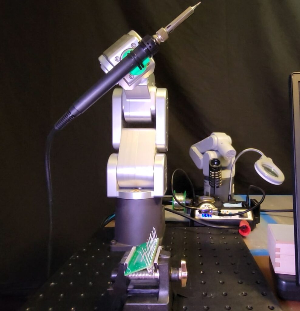
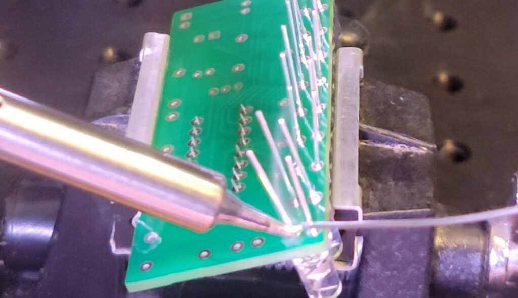
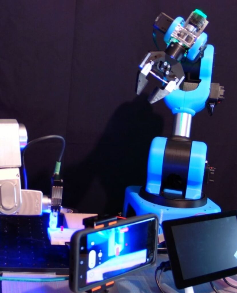
Having a soldering iron, a few build-a-breadboard kits, and a precision robot, it was only a matter of time before I made a robotic soldering video.
In another video- Mecademic Meca 500 Diode Loading Demo – we saw how the Meca 500 had the precision and agility to pick ‘n’ place diodes with delicate, easily-bent legs. The key to placement, I found, was inserting a “shimmy” during the -Z motion; the EOAT essentially “shivers” to ensure the diode legs don’t hang up on the edges of the breadboard ports. Details & code available in my post, “Mecademic Diode Load“
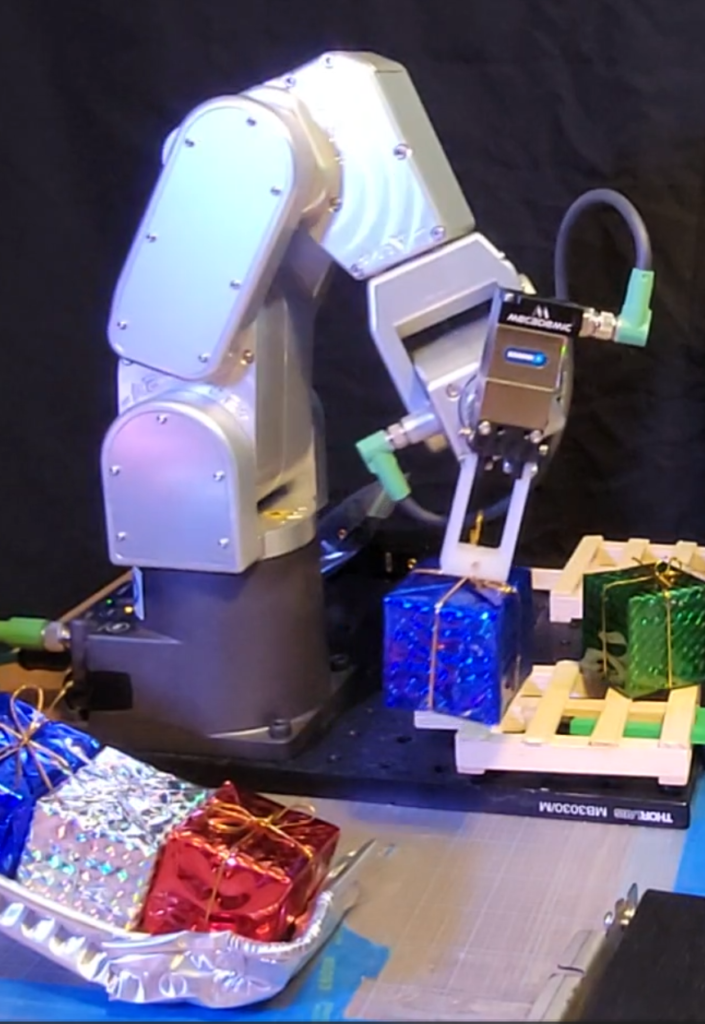
I had intended to print a custom EOAT to grip the soldering iron, but had an extra-long print running at the time ( base adapter for our new Elephant Robot ); I ended up using a utility EOAT with through holes for zipties to securely attach the iron.
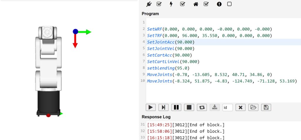
To determine TCP (tool center point), I measured EOAT length to center of iron for Z (35.55mm), and centerline of EOAT to tip of iron for X (96.0mm).
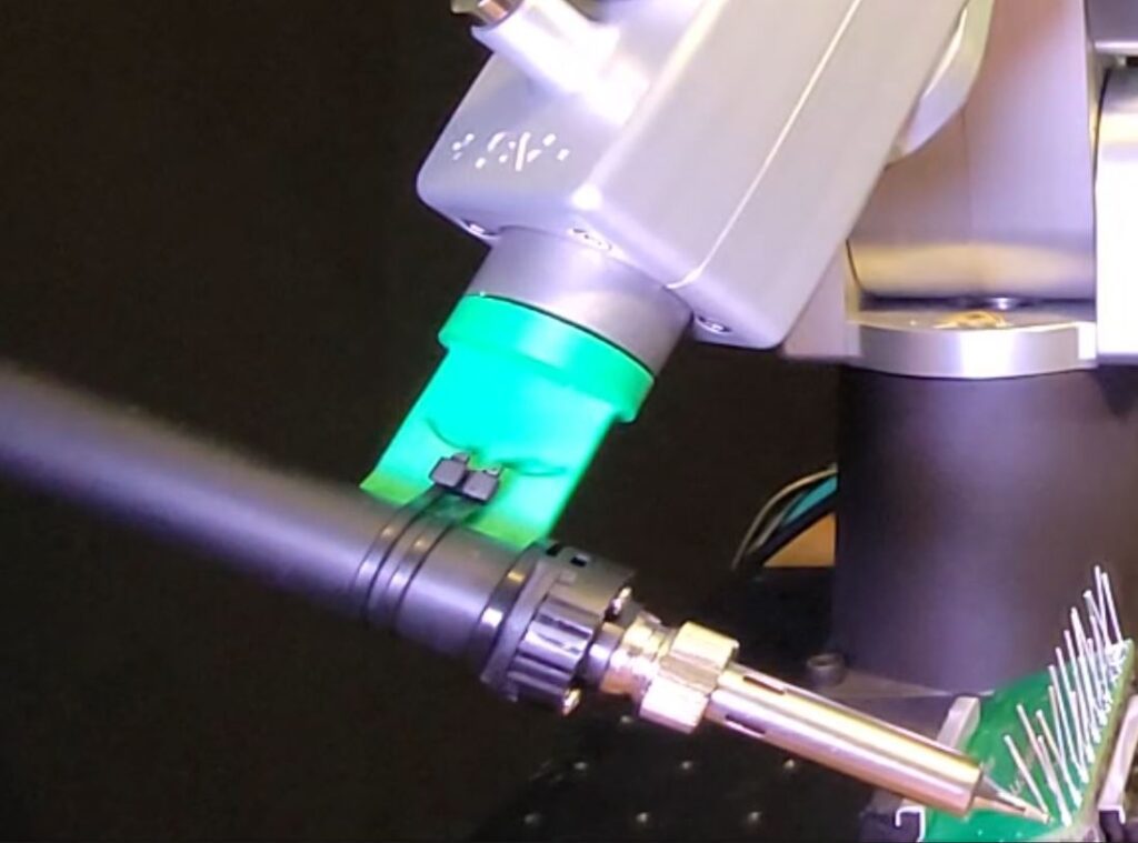
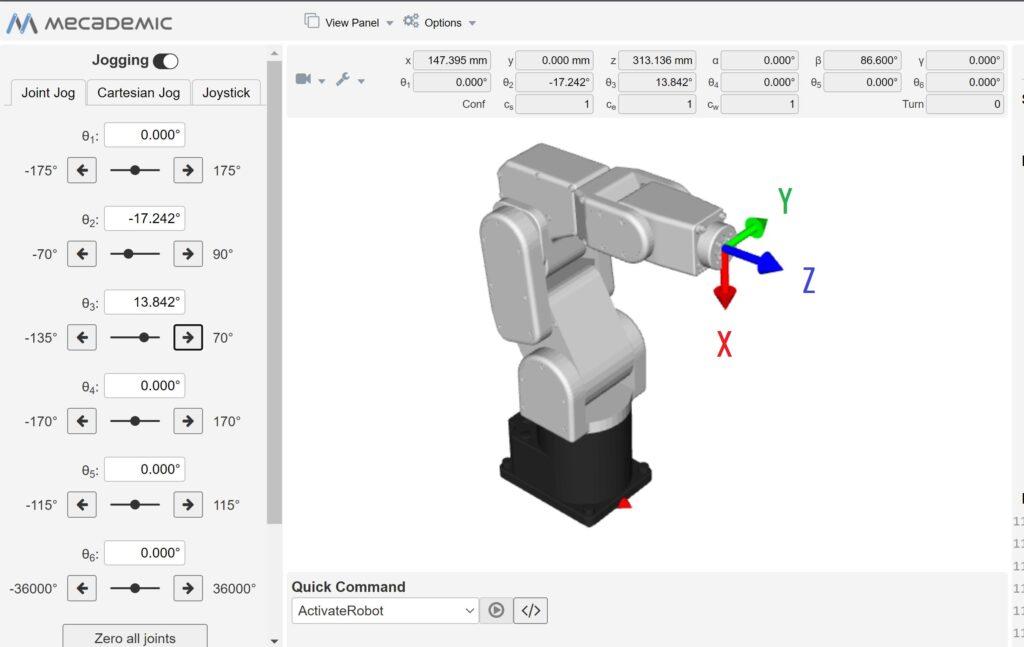
Fine-tuning the smooth motion necessary for the delicate job of soldering is a joy with the Meca 500’s ability to jog in extremely small increments; I practiced on both of the following boards, using the 10 LED board for the video:
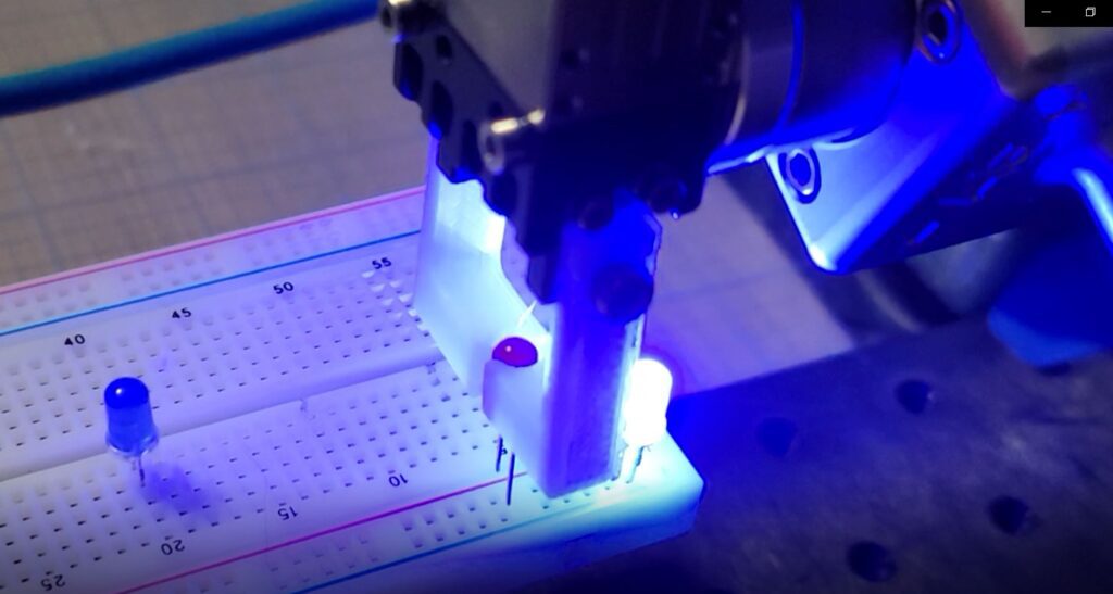
I re-ran the motion sequence several times during filming with the iron off, to make sure the soldering tip wasn’t impacting the diode legs with too much force. I kept the blending value at 0 for the fine motion, as speed wasn’t the goal. The move / safe motion between diode legs is a little exaggerated, so it was more visible in the video.
The cold iron practice has a 1 second dwell at each diode leg. For the segment where I actually solder, I increased the dwell to 2 seconds per leg to make sure a good melt & solder joint was possible.
Here’s the code for both 1 sec and 2 sec dwell soldering sequences:
Disclaimer: As a participant in the Amazon Affiliate program, we earn a small commission if you make a purchase through one of the links in this post, at no additional cost to you.
Best of RoboFiesta – Originally published April 2024
Especially a robot with the exceptional precision & control of the Mecademic 500.
This was just a short trial run, me basically playing around to see if:
It was possible to create a robotic motion which played or “plucked” the tines to produce a tone similar to what is made when a human finger plays the keys, and
The movement of the robot with “safe” position between tines / keys would allow for reasonable pace / rhythm in a short practice tune.
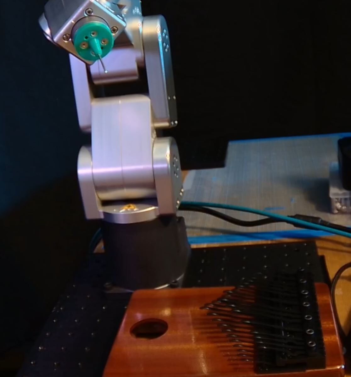
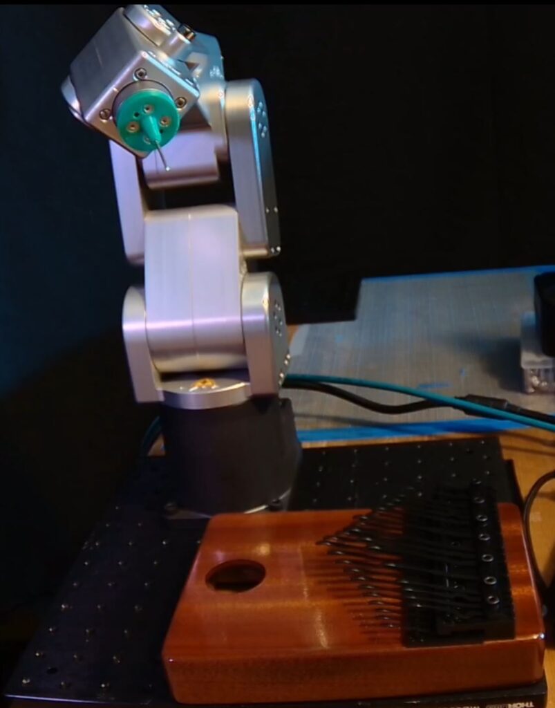
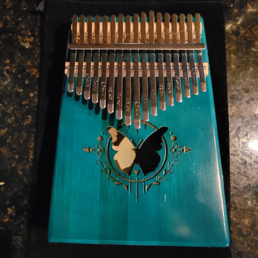
The first kalimba I tried is a nice basic unit with lovely tone, it’s been a lot of fun as an introduction to the instrument.
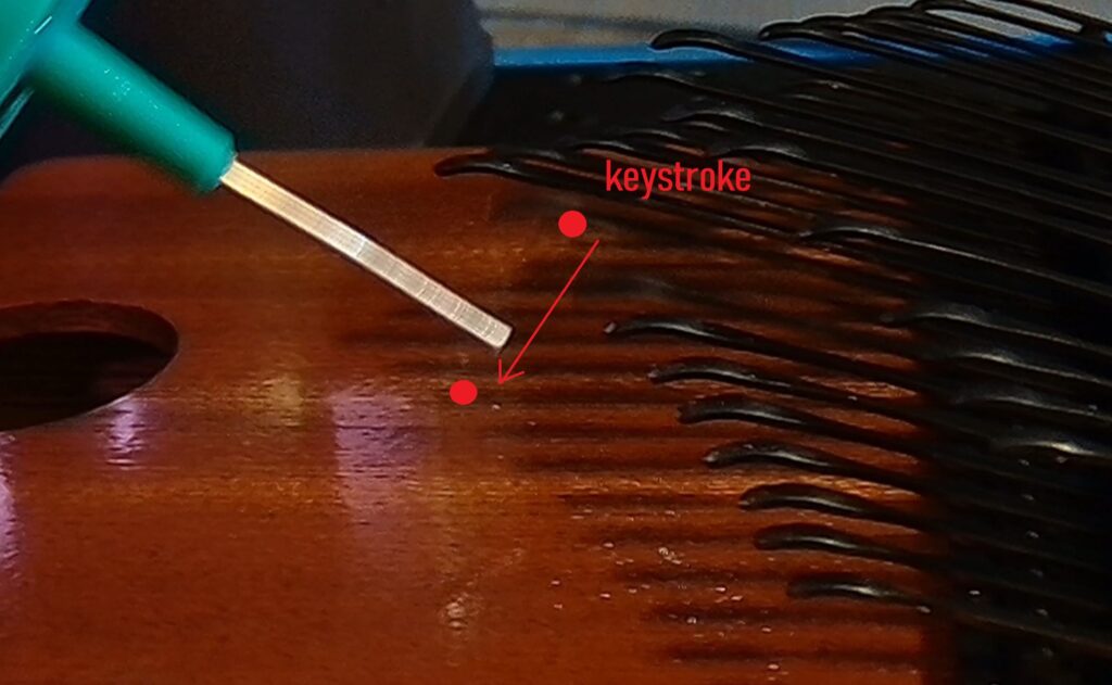
I found that, though not a problem for humans, the tines required a bit too much force for the robot end effector. The 1.5mm aluminum probe tip kept bending after a few keystrokes.
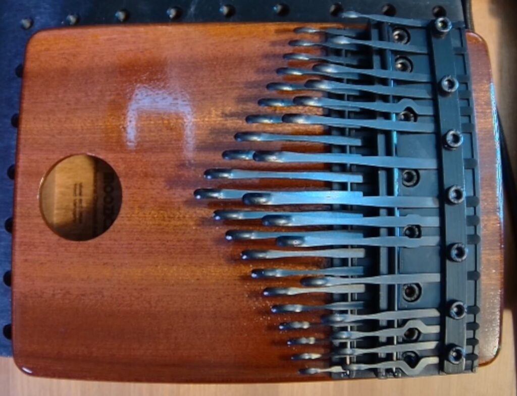
A little searching online found another type of kalimba, this one with a specialized key design that required a lighter touch. It also came in more than 1 variety, with different numbers of tines.
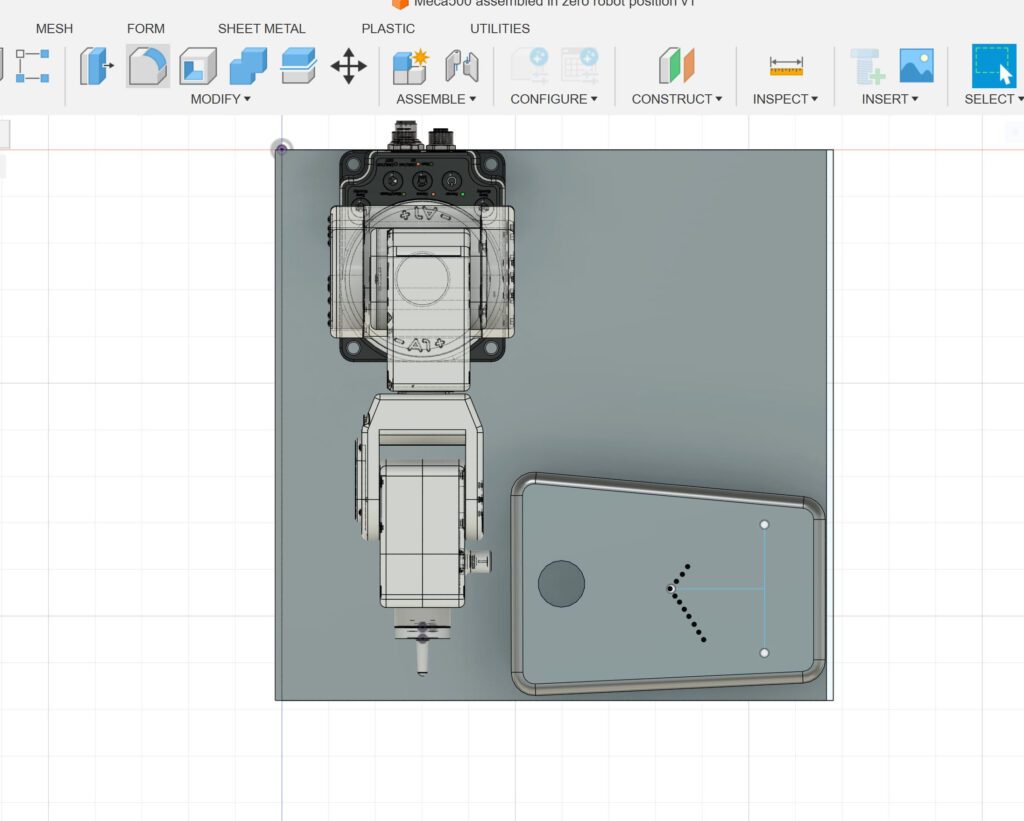
There wasn’t a ready-made .stp file or any CAD available for the kalimba, so I improvised in AutoCad Fusion to make a basic stage layout:
The tines are smaller and more rounded than the first kalimba, which made precision end effector placement & motion critical to tone. Just moving the EOAT vertically in a short rapid motion didn’t work; there needed to be a diagonal component, effectively “sliding” the probe tip off of the tine in a particular manner.
The robot motion was a sequence of move-to positions with some speed changes and delays to produce the timing of the tune. The move-to-safe motion is larger than it really needs to be, but I was concerned about clearances as I moved the blending values higher for smoother / more rapid motion. This is the code I programmed for the short video sequence:
I am working on a better CAD model of a kalimba, with the tines placed accurately. The whole stage could then be imported into a simulator like RoboDK to teach songs or melodies quickly. I did this one by eye, experimenting with different positions & motions to produce the best tones.
Disclaimer: As a participant in the Amazon Affiliate program, we earn a small commission if you make a purchase through one of these links, at no additional cost to you.
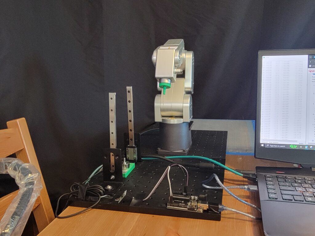
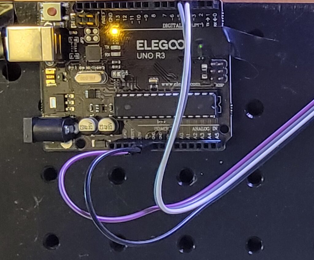
A rainy weekend, a load cell, a robot, and a raspberry pi all got together… ok, this is a small project that is part of a larger project that I’m doing in stages. And, keen eyes will have spotted that the unit in the image above is of the Arduino flavor, as opposed to Raspberry. For more on that, read on.
Initial Setup
I’m a big fan of the Raspberry Pi, and have several Pi4s that have proven very useful and adaptable, so a Raspberry Pi4 was the natural first choice for this project.
I’ve run the Mecademic interface through a Pi before as well, and the robot would be a part of the loadcell demo. I broke out the Pi with display and GPIO board, and went to work.
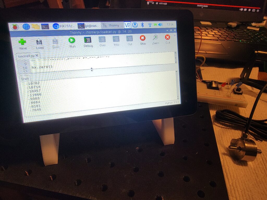
The issue I couldn’t get past when using the Raspberry Pi4 is well known in HX711 circles, it has to do with the timing of amplifier and the sequence of Pi operations; the Pi isn’t really set up for this type of measurements. Even with many measurements for tare & an extensive warm-up time, the values would drift, reset, and drift again; it wouldn’t settle down. There is a better explanation on this Github Readme by tatobari: https://github.com/tatobari/hx711py/
I eventually set aside the Pi4 and started looking at Arduino-type microcontrollers, more on that in the next section.
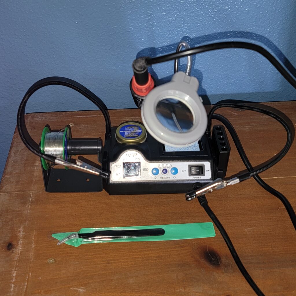
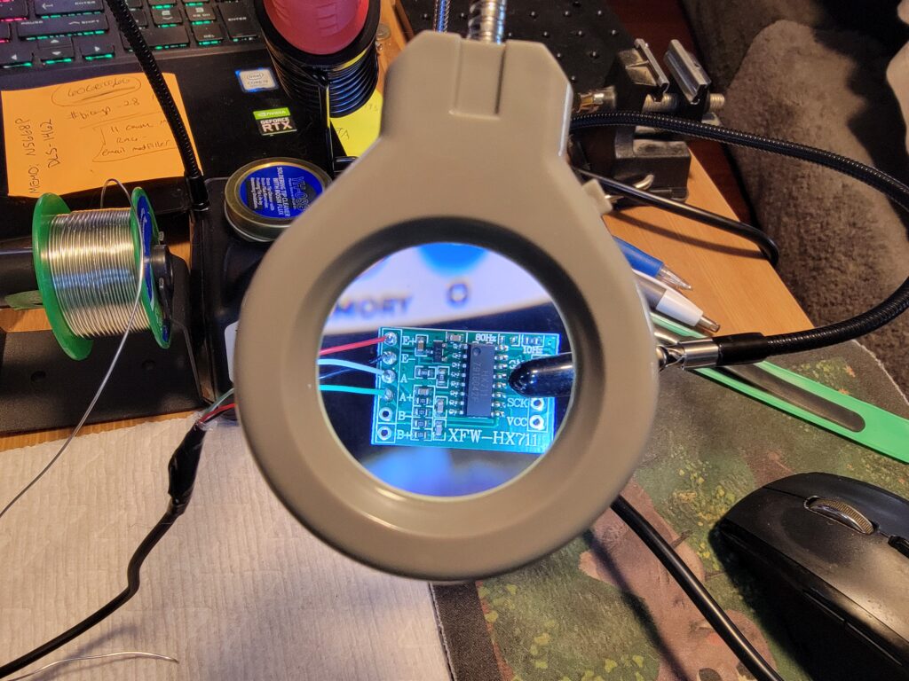
A note about the amplifier- the HX711 is low-cost and readily available, but, if you’re going to incorporate one into a project, do yourself a favor and get a decent soldering iron (if you don’t already have one). I started out using a time-worn old iron I’ve had for years, and damaged 2 amplifier boards before finally ordering a new soldering iron (WEP 927-IV, available here on Amazon). Wow, what a difference that made- I’m really happy with it.
Arduino
I’ve played around with Arduinos in the past, they’ve been around for years, but it’s been a while. I ordered a basic Arduino platform starter kit with the processor and some fun extras I will try out in future: Elegoo Uno R3
The Arduino connects to the laptop through a USB cable. The programming interface is a simple IDE which can be downloaded from this website: https://www.arduino.cc/
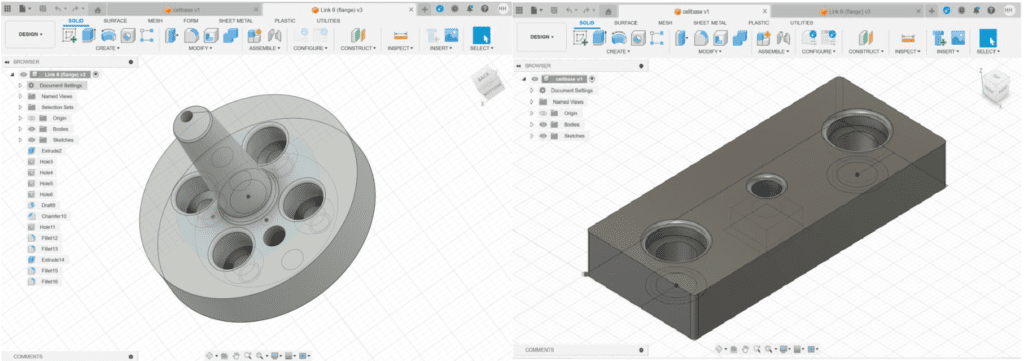
I printed 2 parts for this testing- a new EOAT to hold a 1.5mm aluminum probe tip, and a retainer to fasten the load cell to the optical board.
Testing
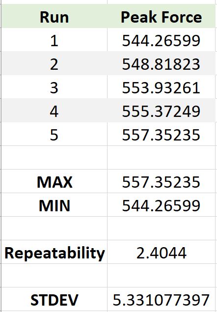
Once the test rig & code were finished, I programmed a brief 5 run sequence for the Mecademic which would place the probe tip at the same position (within a few microns) each cycle. This isn’t a perfect load cell test, but for my hobby purposes works pretty well for the goal of exerting the same amount of force for each run.
The load cell isn’t an expensive one, and I was using a kitchen scale to get the known weight (of a bunch of washers taped together) for tare; not exactly high-tech. Even so, for a just-for-fun hobby-type setup, the measured repeatability of the loadcell in this example is actually better than I thought it would be:
Disclaimer: As a participant in the Amazon Affiliate program, we earn a small commission if you make a purchase through one of these links, at no additional cost to you.
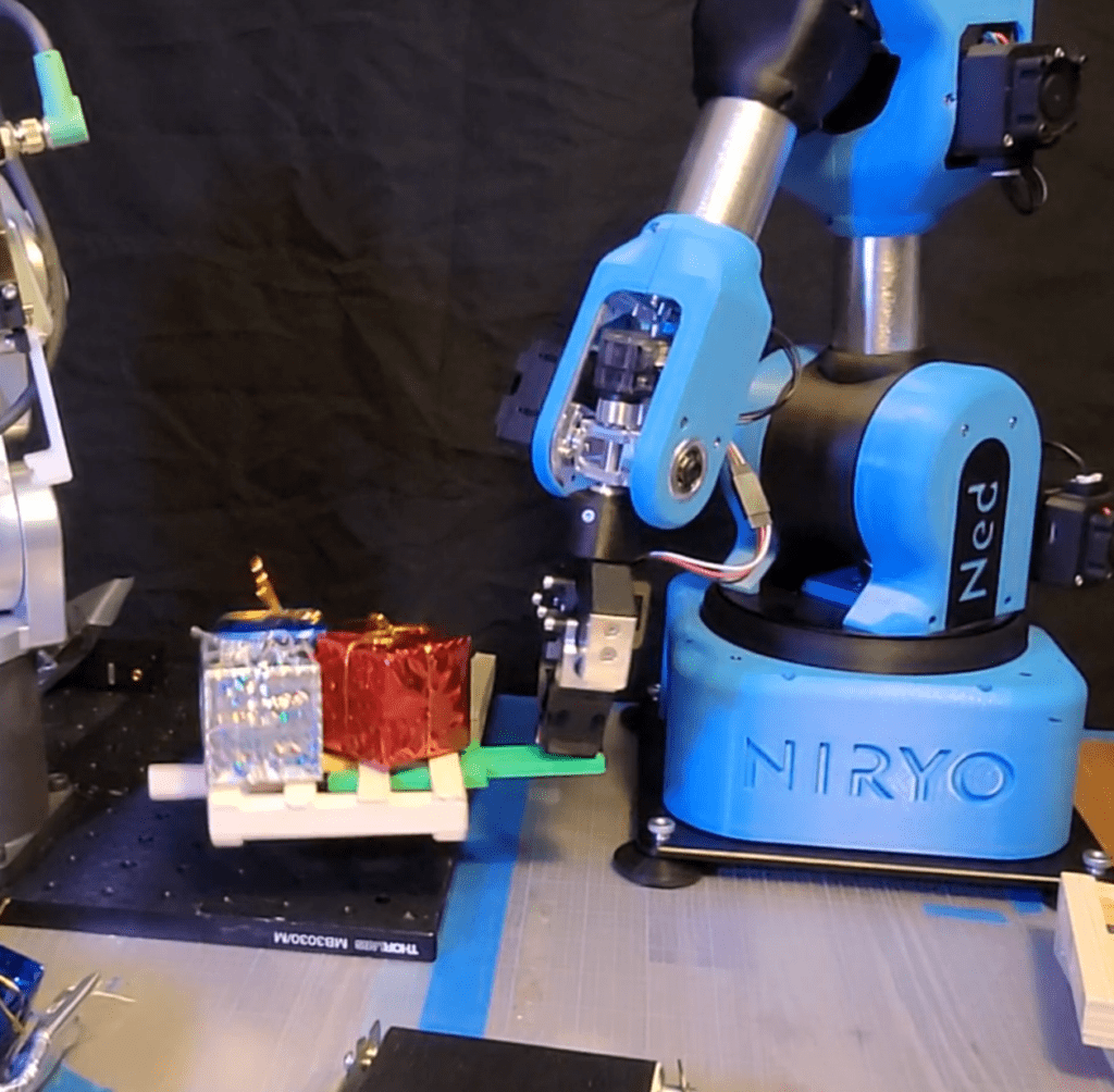
The year has just flown by, and here we are in the Festive Season again. It made sense to do a skit with the robots helping Santa out by palletizing presents (which are then loaded to shipping containers which conveniently fit in Santa’s sled).
OK, so to be truthful I’ve been struggling with some Ned issues for the past few months. He won’t hold a calibration, or for some reason his positioning will shift from one run to the next. The Niryo website has some suggestions, notably updating the steppers:
Maybe that’s the thing to try next, when there’s some time. Anyway, after making a little pallet fork for him, the best I could do was have him statically hold the loaded pallet and pretend that it made it to the conveyor (using editing magic).
Meca Mike was a trooper, and if he had the right grippers could have also moved the pallet after loading it. The challenges for him included irregular placement of the present bows, and a makeshift present slide that didn’t position the boxes very repeatably. It took several attempts to get the pallet load shot.
Here’s the finished video, just a short clip to wish everyone Happy Holidays!
TCP, or Tool Center Point, is a tool which can make your machine set-up less time-consuming by giving you the ability to re-use a set of coordinated instructions between different tools. In this video, I show how to use different TCPs to achieve the same end result with probes of different lengths.
Playing around with TCP settings on the Mecademic one day, and this morphed into the thought that it would be fun to have a robotic sporting match to showcase this very useful function.
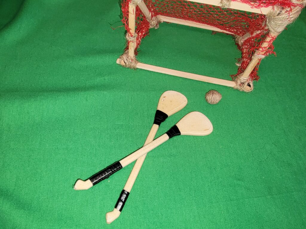
Basketball was out (couldn’t figure out how to dribble the ball repeatably), and soccer didn’t seem practical given the lack of legs in the participants. Irish Hurling came to mind while contemplating ice hockey (the hurley and the hockey stick have vaguely similar shapes).
Ok, so we have the sport identified, now what about props… The first time I watched a hurling match, I was sure the hurleys must have a scoop-type feature to keep the sliotar in place as the players raced up and down the field. The face of the hurley is in fact NOT concave, it’s the skill of the hurlers (camogie-ers?) and the slightly raised stitching on the sliotar that keeps it in place. It’s as if the players have their own TCP functions to keep the center point firmly in the middle of the flattened end of the hurley!
Here’s a great YouTube video from GAA MAN with players demonstrating their hurling skills: https://youtu.be/44Gi2IarBiI
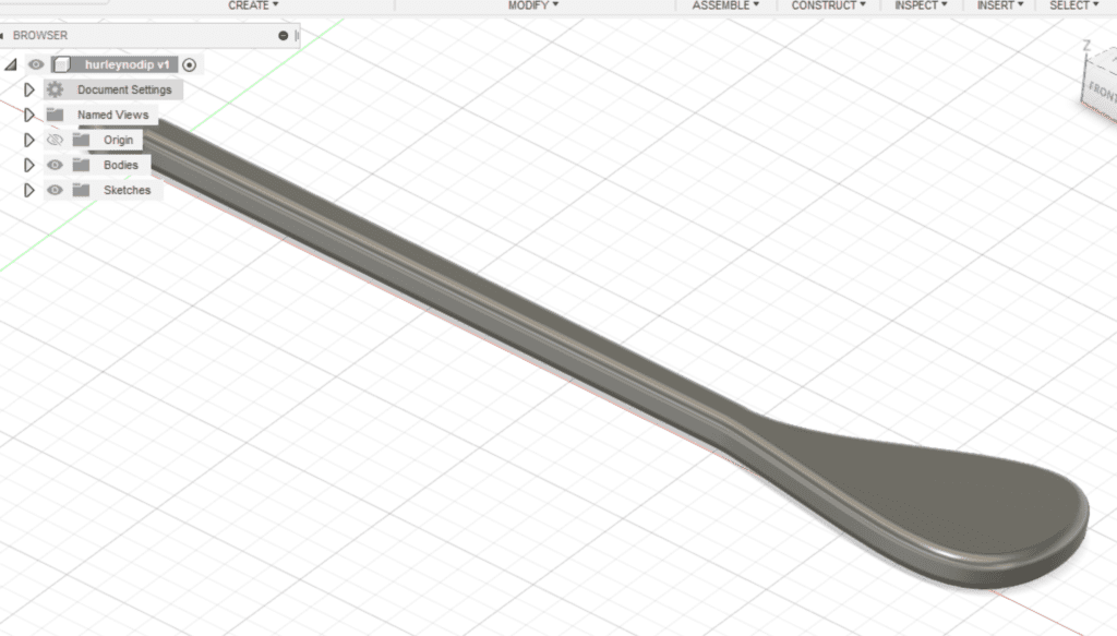
Amazingly enough, miniature hurleys and sliotars aren’t for sale on Amazon or Etsy (and I did a lot of searching). Looking at some online images, I designed a model hurley in AutoDesk 360 that at least keeps the shape, if not proportions, of the real thing. Here’s a great intro to AutoDesk Fusion 360 if you’re not already a user: AutoDesk Fusion 360
I ended up printing the hurleys both ways; in the video, the Mecademic’s hurley is flat while Neds and the xArm’s have one flat, and one concave side.
The hurley strapping is electrical tape.
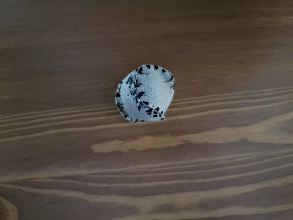
OK, now for the sliotar… I spent an inordinate amount of time trying to stitch a tiny canvas ball, but the material shredded in places. Next, I cut up an old pair of leather gloves and tried sewing a leather one using a tiny baseball pattern. It turned out more square than spherical:
Ned actually liked this one best; it didn’t roll at all, so was easier to hold on the hurley.
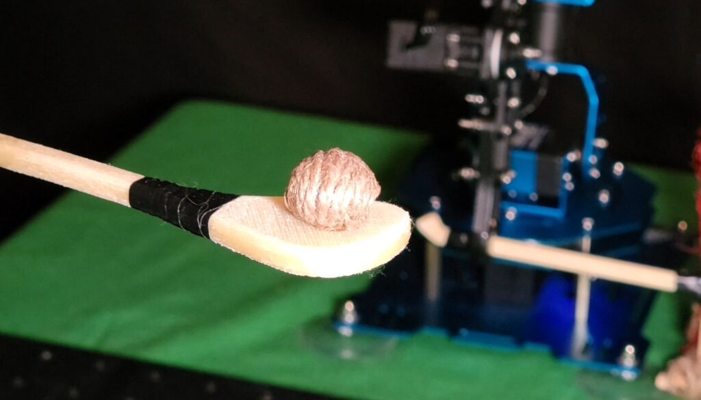
The final sliotar was a design based on some historical sliotar images on the National Museum of Ireland’s website. They were made of cow or horse hair. A ball made of coarse twine seemed about as close as I was going to get; once the glue set, it was hard and rolled reasonably well.
The goal was cobbled together using twine and mesh netting on a wooden frame.
Programming the winning goal motion on the Mecademic was a challenge; suffice to say, acceleration settings were key. Once the proper settings were found, though, Mike made the goal in ~ 75% of the shots. Here’s the final program used in the video:
In many automated assembly applications, a well-thought-out custom gripper design is essential. In this article I’ll talk about the process and iterations needed to accomplish the Meca 500 Diode Load sequence in RoboFiesta’s Mecademic Meca 500 Diode Loading Demo on YouTube.
Some of the things you’ll need to consider are:
What’s being gripped / picked. Dimensions, fragility, prestage setup
Speed required for the application
Precision / repeatability required for the application
Incoming material variability
Placement location with regards to EOAT orientation
EOAT will change depending on material being handled, and pick/place location considerations
For a part in a given location / orientation- a diode mounted on a breadboard, for instance- the gripper design would need to change depending on which direction the gripper fingers extend from the gripper mechanism.
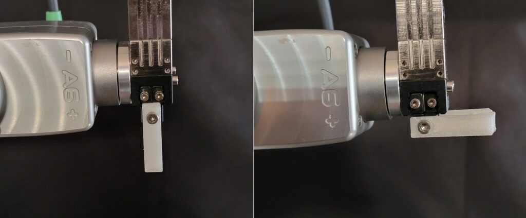
It’s a good idea to do some dry runs with mock material to determine the requirements. For the diode handling, we could have picked with the gripper fingers extending in either X or Z from the mechanical gripper body mounted on the robot flange:
Which directions the gripper fingers extend also affects the toolpath you will program. In our diode sequence, the gripper fingers extend down in X from gripper body.
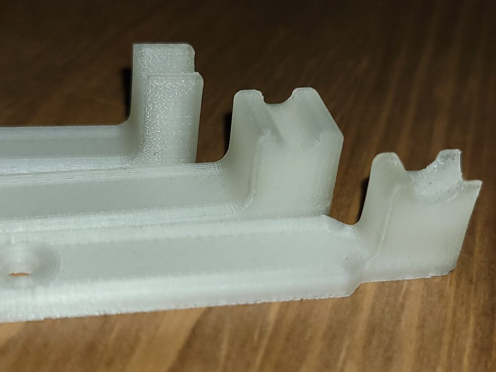
It took several iterations of grippers to develop a design that would firmly grasp the slightly tapered diode body without slipping. The final design featured a small relief or notch feature to accommodate a small lip on the bottom of the diode body.
Gripper with relief feature for diode lip
Finally, having a capable 3D printer like the Flashforge Creator Pro is invaluable for on-the-fly iterations for functionality and changes in setup orientation of your grippers. I’m currently using 1.75mm ABS Transparent filament, it’s a great material for general purpose applications.
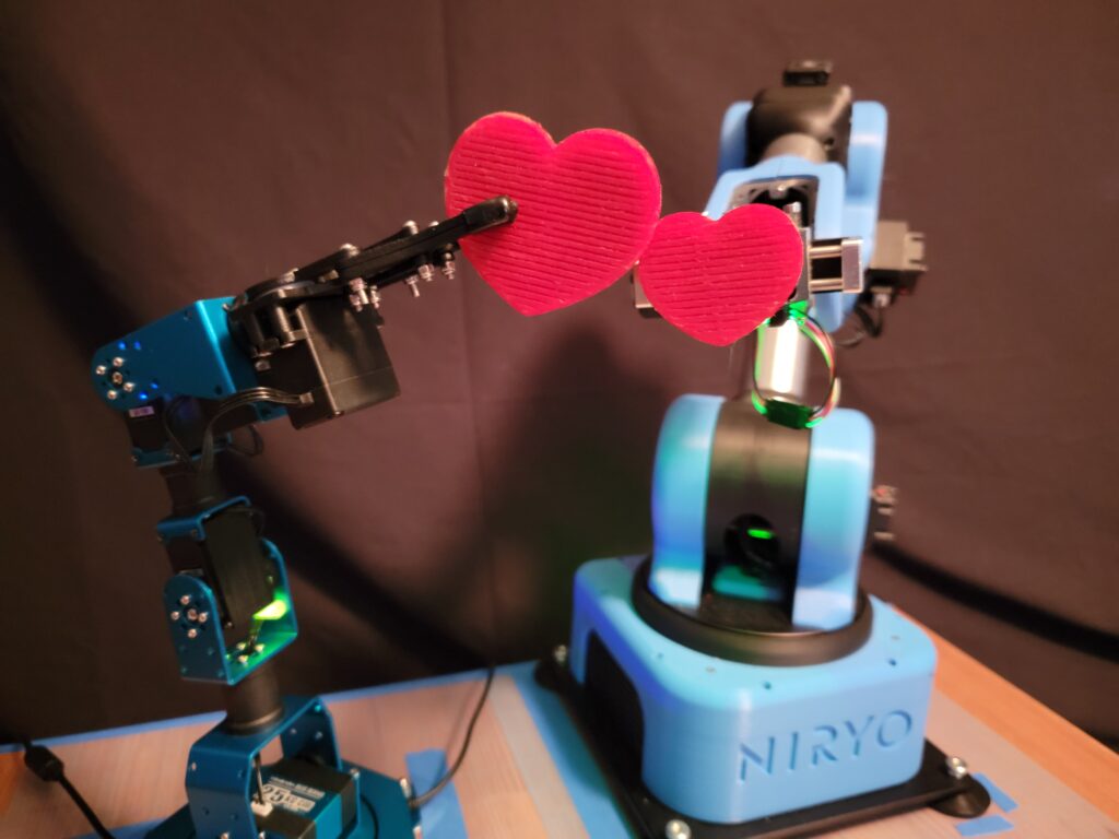
Ned has a new friend! The HiWonder Xarm is a fun little educational robot which you can buy assembled or in a kit. We thought it would be fun to see if the Xarm is repeatable enough to perform in a video alongside our Niryo Ned. It did very well for the price; at one stage, I needed to reteach some points that “wandered” for some reason but other than that it’s a great little robot. Note, the Xarm is really more of a 5-axis than 6-axis robot; the 6th axis is the gripper jaws, which does limit some of the positioning but Ned was able to work around this.
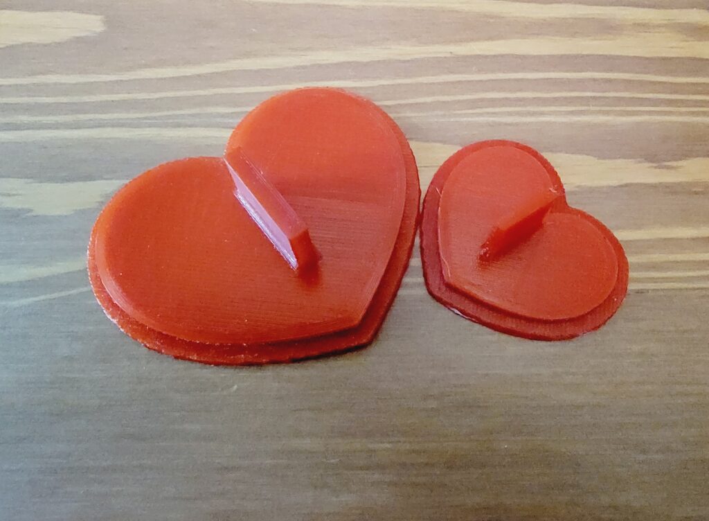
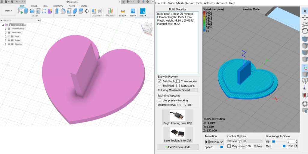
For props, I designed a simple heart shape with a grip and printed it on our FlashForge Creator Pro. Resized for the smaller heart, repeat. Slicing done on Simplify3d.
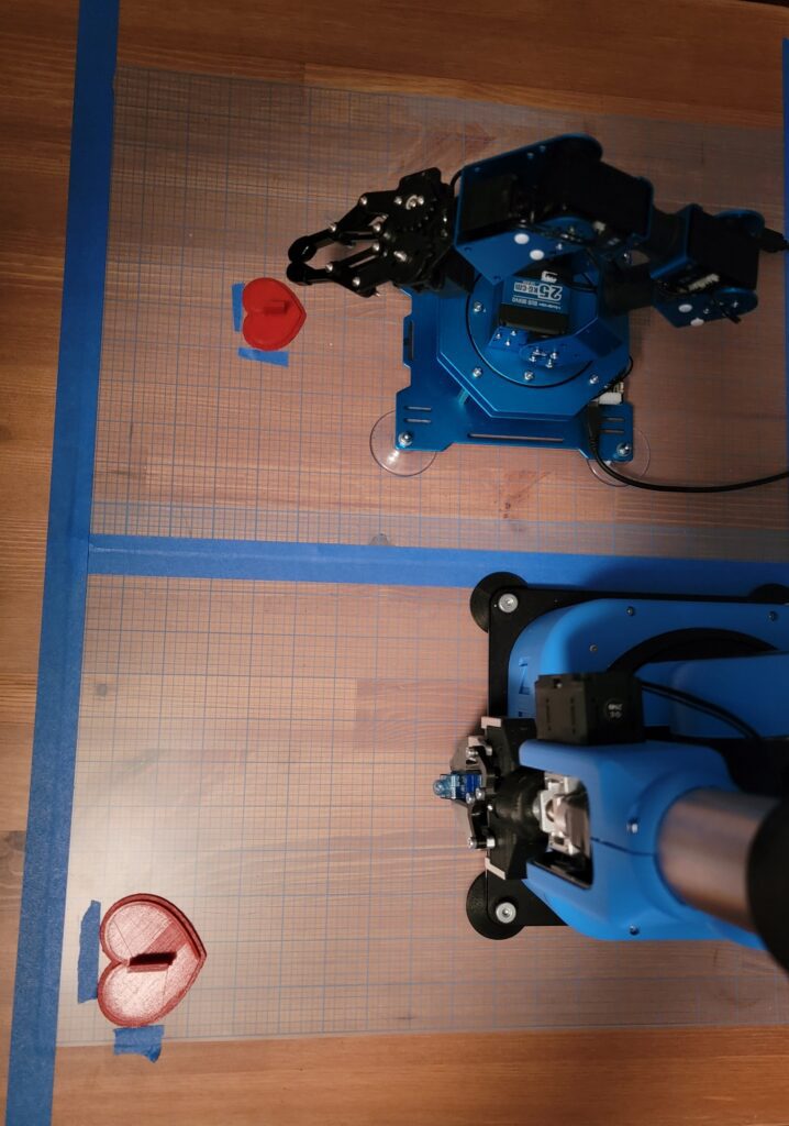
In any setup where pre-stage is the locating method, it’s important to know where your robots & parts are. I used a couple of plastic grids which are inexpensive and reusable; they’re sold as quilting accessories.
Using a grid for repeatable prestaging
We repeated the exchanging-of-valentines action over two dozen times; occasionally it didn’t work out (there was some variability where Ned put down the small heart, and occasionally the pencil stuck in his gripper jaws), but overall I was really happy with the sequence. The video featured on RoboFiesta’s Youtube channel was shot on a Samsung Galaxy S21 Ultra 5G, which has awesome media production capabilities. Edited on Adobe’s Premier Pro.
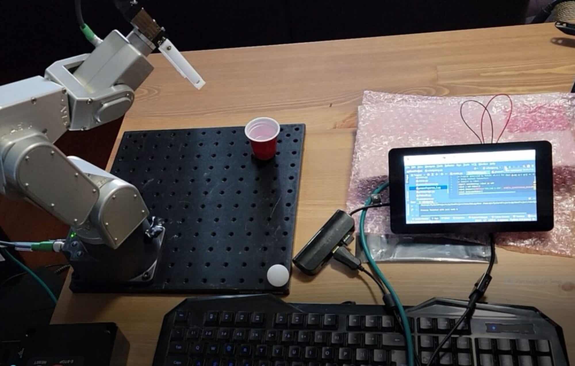
With 5um repeatability, the Mecademic 500 is uniquely suited for applications requiring a high degree of precision. Prestaging of components is key, however, when using purely motion with no vision or dynamic location. The CanaKit Raspberry Pi breadboard provides a good stage for this work, which could be adapted for backloading & soldering manufacturing applications. Watch the video here.
Battered Diode
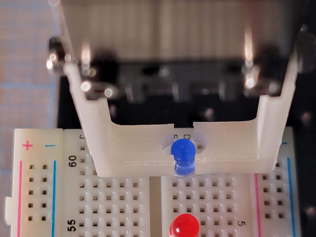
Word of warning- have a few “burner” parts for use during setup. Once the diode legs get bent they are difficult to straighten!
It’s difficult to see, but the robot performs a “shimmy” action as it places the 2 diodes. This utilized the Mecademic’s ability to jog in very fine increments when building the program- in this case, 0.05mm and finer. This motion was to offset the variance in prestage presentation of the diodes, and the spring memory in the fragile diode legs. The program is included below.